
Four Approaches for Automation of Inspection of Sheet Metal component and Assemblies
Four Approaches for Automation of Inspection of Sheet Metal component and Assemblies
Background
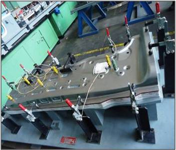
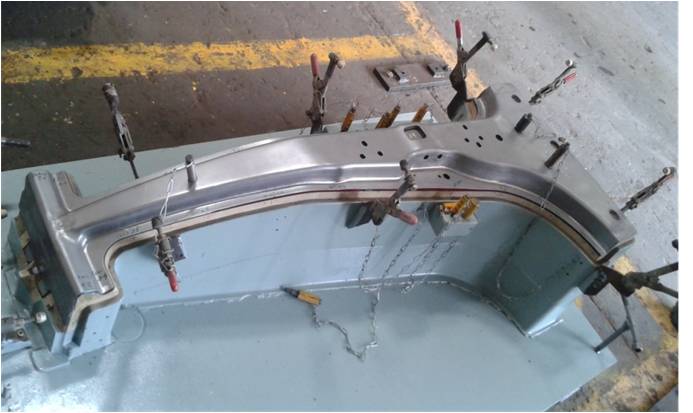
As per conventional practice in sheet metal manufacturing industry, manual inspection fixtures are used as follows:
- Component / assembly rests at few small mating surface patches with location features
- It is clamped manually at certain points.
- The location and size of holes is checked by passing provided pins.
- The edges are checked with feeler gauge with reference to matching profile at the fixture.
- The traceability and inspection reports (if at all) are manually ensured.
- The process is too slow to be in-line with mass production; usually it is done for initial proving, on sampling basis and for resolving quality disputes.
Requirement
With drive for achieving “World Class Quality” and for detecting and arresting any flaw at first appearance there is pressing need for automation of “in-line” inspection and its integration with Production Monitoring System, ERP and Manufacturing Automation Equipment. There are 4 approaches for implementing the same.
Approach 1: Augmentation of existing Inspection Fixtures with Control Logic
- Microswitch / Proximity switch sensing is provided under each passed pin, for component presence sensing and for sensing of clamping.
- A graphic LED panel shows all complying points
- Further a PLC may be added for reading / branding the component i/d
- It may also brand / damage faulty component
- It could communicate the Quality records to host computer / server or even on Cloud generating a statistical record of specific failure points
Limitations
- Oversize holes may pass off as OK
- Edge matching, wrinkles, thinning and tearing would still have to be manually recorded through HMI
- It is “Go/No-Go” checking and cannot generate any statistical measuring data for SQC or determination of Cp/Cpk
Approach 2: Augmentation of existing Inspection Fixtures with Gauging Functionality
- In process Gauging instrumentation and Data Acquisition function is integrated with Fixture
- Probes employing various technologies and precision levels may be used. E.g., LVDT, Strain Gauge based, Piezo, capacitive/inductive gap sensing.
- Clamping and measuring cycle may be automated for in-line use.
- Micron level precision may also be achieved.
Approach 3: Use of Laser Distance Measuring
- Number of Laser Distance Measuring Devices may be mounted in Inspection Windows of a Line.
- Some identified points may be measured in 1mm accuracy level as the production flows.
- Alternatively single Laser Distance Measuring device may be mounted on position controlled motion system whereby it could digitize the programmed contours.
- The motion system could also be an existing CNC Machine and it could be programmed to digitize profiles covering the features of interest. Enclosed video clipping illustrates use of such as device in conjunction with a CNC machine for scanning and replicating a sculpture.
Limitation
- Device measures in one axis only.
- It could be used for coarse measurement only.
- Usually it could only be used for alignment and setting up rather than inspection.
- Use of Laser Radar at BIW Line
Approach 4: Use of Robot based Scanners
- White Light / Blue Ray Scanners are mounted on two Robots on either side of Line
- Full surface scan is recorded
- Comparison of point cloud with CAD model generates visual reports in color fringes
- Teach-in method is used for inspection program generation
- Could also be complemented by Gap-Flushness checking device on Robots
Limitations
- Precision level is 0.05 to 0.1mm mm which may be good enough for sheet metal but not for metrology grade inspection.
- It primarily generates free form surface digitizing, the metrology report of geometrical elements with GD&T is entirely based on computation and post processing
- Edges, holes and bores ( in case of solid blocks ) cannot be faithfully measured.
- Thickness/Thinning determination may not be accurate enough.
Conclusion
A judicious mix of these approaches could be used depending on budget, precision level, technology and process requirement, as long as there is compatibility of overall data integration.
Certain Quality parameters pertaining to aesthetics, wrinkles and optical defects would still have to be manually entered in through HMI at various stations.